
When Fitment and Alignment Matter More Than the Print Itself
How a custom ultrasonic display led us to rethink our CAD design, reduce assembly tolerances, and make better use of 3D printing.
3D printing gives designers enormous freedom. Parts that would otherwise require several machining operations, custom tooling, or complicated assembly procedures can often be produced in a single print.
But just because a part prints successfully doesn’t mean it will perform as intended.
This is something we encountered while working on a custom ultrasonic standing-wave display. The project required several ultrasonic transducers to be positioned accurately in a 3D printed frame. Our first design used separate mounting components that could be printed and assembled individually. It seemed like a practical approach, until we started considering how the parts would actually fit together.
The issue wasn’t the complexity of the geometry or whether our printer could produce it. It was the cumulative effect of small dimensional variations at each connection.
We eventually revised the design to incorporate the critical mounting features directly into the frame. It was a relatively simple change in approach, but it addressed several problems at once.
Here’s how we arrived at that decision and what the experience taught us about designing functional assemblies for FDM 3D printing.
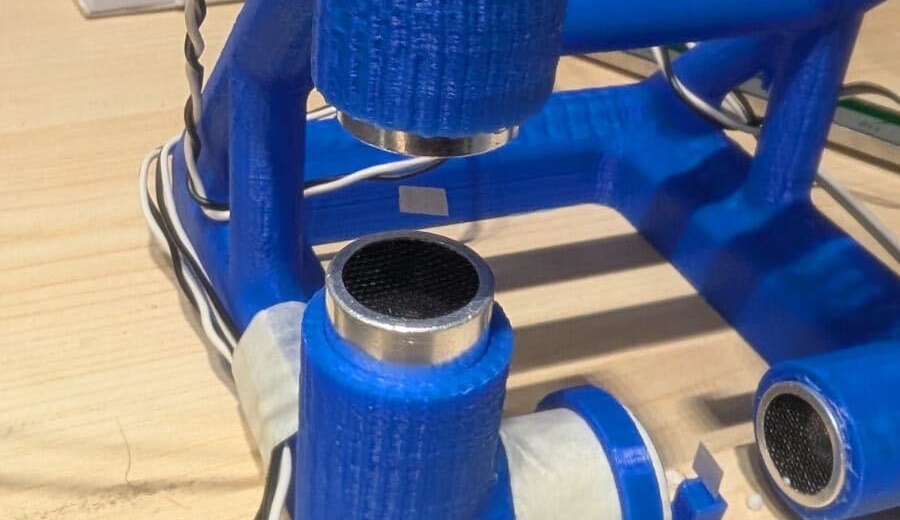
Figure 01 — Ultrasonic Wave Levitation Excitation Display.
The Project: Building an Ultrasonic Standing-Wave Display
The client wanted a demonstration setup that could use ultrasonic sound waves to suspend and manipulate small pieces of paper.
The system used 40 kHz ultrasonic transducers arranged in opposing pairs. When driven at the appropriate frequency and phase relationship, the sound waves from opposing transducers can interact to establish a standing-wave field.
Under suitable conditions, acoustic forces within this field can trap lightweight objects, allowing them to remain suspended without direct mechanical support.
The display needed to demonstrate this effect in two orientations:
Vertically: One transducer facing upward and another downward, with the paper suspended between them.
Horizontally: Two transducers facing each other from opposite sides, with the aim of holding small paper pieces upright within the acoustic field.
The electronics were only part of the challenge. We also needed a mounting structure that would maintain the transducers’ relative positions.
The spacing between the transducer faces, their orientation, and how closely their central axes lined up all mattered.
At 40 kHz, the wavelength of sound in air is approximately 8.6 mm at room temperature. Changes in transducer separation can therefore affect the acoustic field, while angular misalignment or lateral offsets can alter the interaction between the opposing sound beams.
This made the printed frame more than just a convenient way of holding the components. Its geometry had a direct influence on the experiment.
Our First Design: A Modular Frame with Separate Mounts
Our initial CAD design used a supporting frame with separate tubular, elbow-shaped housings for the transducers.
Each housing would hold an individual transducer and attach to the main structure. The frame would establish the general layout, while the removable housings would make it easier to install and position the electronics.
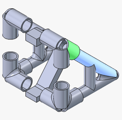
Figure 1 — Initial CAD design (V1), showing the supporting frame and separate tubular transducer housings.
There were good reasons to start with this arrangement.
Smaller components are generally easier to print, particularly when their geometry would otherwise require extensive support material. Separating the housings also meant we could make adjustments to individual parts without reprinting the entire assembly.
If a transducer didn’t fit properly, for example, we could modify its housing and print a replacement.
From a prototyping perspective, that flexibility was appealing.
The problem was that we had introduced several connections between the features that actually needed to remain aligned.
Each printed housing had its own dimensional tolerances. So did the openings and mating surfaces on the supporting frame. Even if every component looked acceptable on its own, the assembled structure could still introduce unwanted variations in the transducers’ final positions.
That became the main concern with V1.
Where the Design Started to Fall Short
In CAD, mating parts have perfectly defined geometry. A cylindrical connector is circular, a mounting surface is flat, and two aligned features share exactly the same axis.
FDM printing doesn’t reproduce those ideal conditions perfectly.
Dimensional accuracy depends on factors such as printer calibration, extrusion settings, material behavior, print orientation, and cooling. Surface finish can also vary significantly between different features of the same printed part.
For most projects, these variations can be accommodated through suitable clearances and tolerances.
In our case, however, the printed interfaces were doing two jobs. They had to connect the components mechanically and establish the orientation of the transducers.
This made the fit between the parts especially important.
Small Errors Add Up
Consider the path from the main frame to the face of a transducer.
First, the tubular housing has to fit into its corresponding opening. The housing then needs to sit at the correct angle. Finally, the transducer itself must fit into the housing without being tilted or positioned off-center.
Each connection introduces some possibility of error.
A slightly oversized opening might allow the housing to rotate. An uneven mating surface could prevent it from seating squarely. The transducer could also sit at a small angle inside its socket.
Individually, these differences might be difficult to notice. Together, they could shift the transducer away from its intended position.
This is an example of tolerance stack-up, where dimensional or positional variations across multiple components contribute to the final assembly error.
Not every error necessarily adds in the same direction, but the more interfaces involved, the more relationships need to be controlled.
In our V1 design, the alignment of two opposing transducers depended on several printed components fitting together consistently.
Even a connection that felt tight could leave the transducer slightly misaligned.
That was an important distinction: a secure mechanical connection doesn’t automatically guarantee accurate positioning.
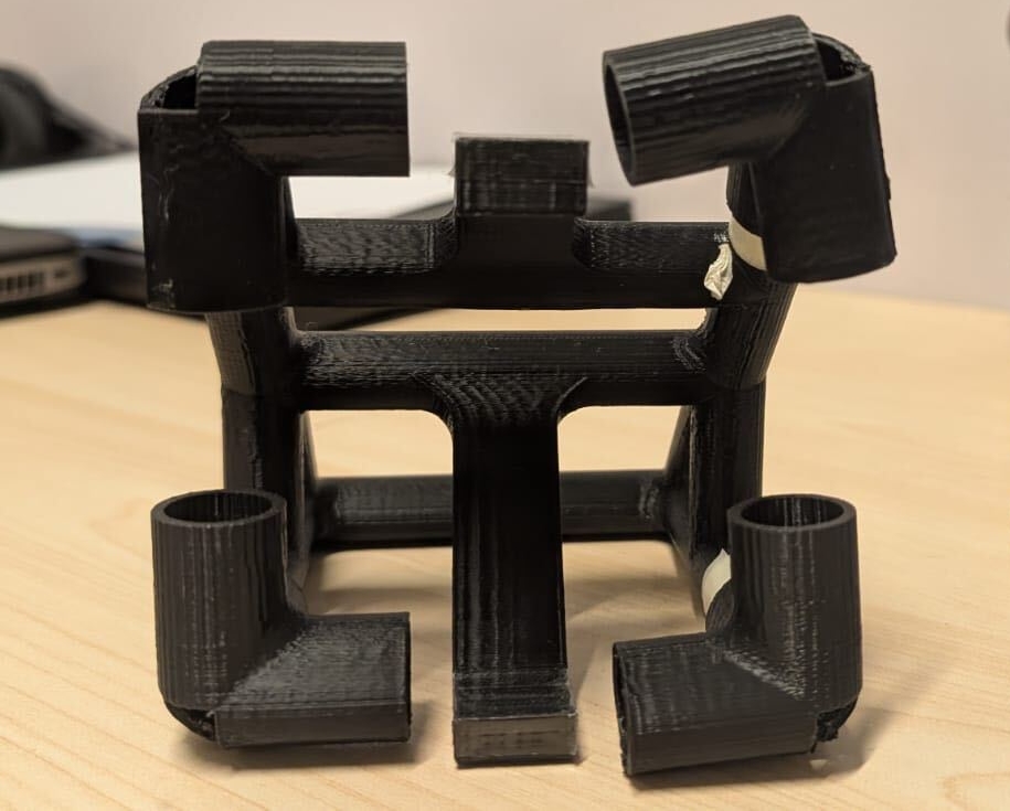
The Tube Ends Were Particularly Difficult
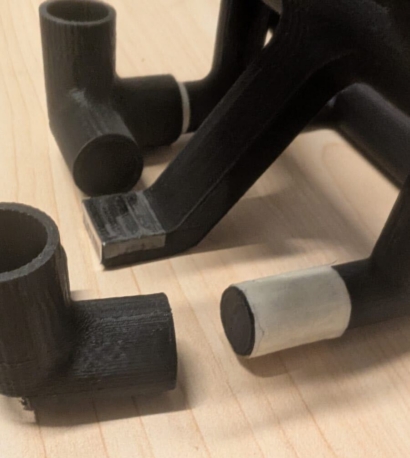
The tubular connector geometry introduced another complication.
FDM printers build parts one layer at a time, and the resulting accuracy of a cylindrical feature depends partly on how it is oriented during printing.
A vertically printed hole, for instance, may behave differently from a horizontal one. Unsupported regions, layer transitions, extrusion variation, and first-layer expansion can all influence the final dimensions and surface finish.
The tube ends in our design were particularly sensitive because they also served as mating features.
Small irregularities around their openings or contact surfaces could affect how the housings seated against the frame.
This meant we couldn’t judge the quality of the design simply by checking whether the connectors fitted into their respective openings.
We also had to consider whether they would consistently seat at the intended angles.
We could have tried to improve the fit through tighter clearances, additional locating features, or more post-processing.
But that would mean spending time improving several joints whose main purpose was to position components that could potentially be mounted directly in the frame.
That prompted us to revisit the design.
The Second Design: Making Alignment Part of the Frame
For V2, we changed the way we approached the assembly.
Instead of keeping the transducer housings separate, we incorporated the alignment-critical mounting geometry into the primary structure.
The idea was to have the frame define the intended positions and orientations of the transducers, rather than relying on several independently printed connectors to establish those relationships during assembly.
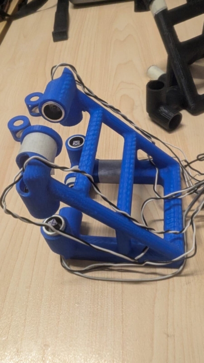
This removed several of the interfaces present in the original design.
In V1, the final position of each transducer depended on the combined accuracy of its housing, the connecting features, and the way those components were assembled.
In V2, much of that relative positioning was built into the geometry of the frame itself.
There were still manufacturing tolerances to consider, of course. Integrating features into one printed body doesn’t guarantee perfect dimensions. Warping, shrinkage, or an incorrectly sized mounting hole can still affect the finished part.
But it does remove some of the opportunities for independently manufactured components to shift, rotate, or seat differently during assembly.
It also simplifies the process of installing the transducers because fewer separate components need to be positioned and secured.
For this project, that was a worthwhile trade-off.
We gave up some of the flexibility of individually replaceable connector housings in exchange for a simpler assembly with fewer alignment-dependent joints.
Figure 3 — Revised CAD design (V2), with the transducer mounting geometry integrated into the main structure.
Why an Integrated Design Made More Sense Here
Modular assemblies are useful, and there are plenty of situations where we would still choose them.
Separate parts can be easier to replace, maintain, modify, or manufacture. They also allow designers to combine different materials or provide adjustment where it’s needed.
But modularity introduces interfaces, and those interfaces need to be designed just as carefully as the components themselves.
A joint may require a fastener, a locating surface, a press fit, or some other method of controlling how the parts sit relative to one another.
When the joint influences the position of a functional component, its accuracy becomes part of the overall design.
In a conventionally manufactured assembly, locating pins, machined shoulders, and precisely bored holes might be used to control those relationships.
With 3D printing, we have another option.
Since FDM can produce fairly complex geometry without dedicated tooling, features that would otherwise be manufactured separately can often be incorporated into a single structure.
That doesn’t mean everything should be made in one piece. Large integrated parts can be more difficult to print, and a damaged feature may require replacing the entire component.
There are also situations where adjustability is essential. If our ultrasonic display required frequent changes to the transducer angles or spacing, adjustable mounts might be the better solution.
But where a set of components needs to maintain a fixed geometric relationship, an integrated structure can reduce the number of things that might go wrong during assembly.
In our case, eliminating unnecessary mounting interfaces was more useful than making every individual component removable.
What This Means for Functional 3D Printed Parts
Although this project involved ultrasonic transducers, the same considerations apply to many other 3D printed assemblies.
Think of a gearbox housing. The individual components might all print successfully, but if the bearing seats are misaligned, the gears and shafts may not run properly.
A robotic arm has similar concerns. Small amounts of play or angular error at its joints can influence positioning accuracy, particularly as the arm extends.
The same principle applies to optical mounts, sensor housings, linear guides, and fixtures used to hold parts during manufacturing.
In all these examples, the important question isn’t simply whether the parts can be printed.
It’s whether the finished assembly maintains the geometric relationships required for the system to function.
That should influence how the CAD model is developed.
Before dividing a design into printable components, it helps to identify which dimensions and relationships are functionally critical.
Which features need to be concentric? Which surfaces must remain parallel? Which components require a fixed distance between them? Where is adjustment useful, and where would it only introduce another potential source of error?
Answering these questions early can prevent unnecessary complications later.
For the ultrasonic display, the critical relationships were the transducer spacing and alignment. Once we treated those as the starting point, the advantages of integrating the mounts into the frame became much clearer.
What We Learned from the First Prototype
One reason 3D printing is so useful in product development is that it allows designs to be tested and revised without committing to expensive tooling.
Our first version was a reasonable starting point. We prioritized ease of printing, modularity, and the ability to replace individual components.
It was only when we examined the physical fitment and alignment requirements more closely that the limitations of this approach became apparent.
The separate tube-end connections were adding complexity to a system that depended on consistent geometric positioning.
Rather than repeatedly adjusting those interfaces, we revised the CAD model to remove several of them.
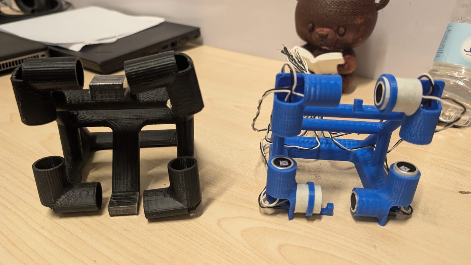
Figure 4 — Prototype assembly and experimental setup showing the transducer arrangement and the role of the printed frame.
This is the kind of feedback that makes prototyping valuable.
CAD software can identify obvious interference problems and verify the nominal dimensions of a design. What it doesn’t automatically tell you is how a particular printer will reproduce each feature or how consistently several printed components will fit together.
Those practical details only become clear when manufacturing constraints are considered and parts are physically evaluated.
Sometimes a design needs nothing more than a small clearance adjustment. Other times, changing the print orientation or adding a locating feature can solve the problem.
And occasionally, the better solution is to reconsider why the assembly was divided into separate parts at all.
That was the direction we took with V2.
Final Thoughts
It’s easy to focus on print quality when discussing 3D printing. Layer height, surface finish, material selection, and dimensional accuracy are all important, but they are only part of what makes a functional printed product successful.
The CAD design determines how those printed features interact once the parts are assembled.
Our ultrasonic standing-wave display was a useful reminder that making individual components easier to print doesn’t always make the final product easier to build or more reliable.
The first design gave us modularity and flexibility. The second placed greater emphasis on maintaining the alignment of the transducers by reducing the number of separate mating components.
Neither approach is inherently better for every application. The right decision depends on what the finished product needs to do.
At Brick3DP, this is how we approach functional 3D printing projects: not simply as a process of turning CAD files into physical objects, but as part of a wider product development process.
Whether we’re producing a custom electronics enclosure, a mechanical prototype, or an experimental apparatus, we look at how the part will be manufactured, assembled, and used.
Because a successful 3D print isn’t just one that comes off the printer looking right. It’s one that fits, assembles, and performs the way it was designed to.