How it Works and Where It Fits in Product Development
Fused Deposition Modelling (FDM), commonly called filament 3D printing, produces physical objects by depositing heated plastic layer by layer. It is used to manufacture prototypes, custom components and small batches of parts without first manufacturing a dedicated mould.
Its usefulness extends beyond producing a physical copy of a digital design. An FDM prototype can help establish whether components fit together, if a product feels comfortable to handle, or whether a mechanism moves as intended. This allows for design validation prior to manufacturing.
How layer-by-layer printing works
The process begins with a 3D digital model, usually created in CAD software. Before printing, a program called a slicer divides the model into thin horizontal layers and generates the paths that the printer will follow.
A spool supplies plastic filament to the printer’s extrusion system. The filament passes into a heated nozzle, where it softens sufficiently to be deposited as a controlled line of material. The nozzle follows the programmed path across the build surface, forming the first layer. Subsequent layers are deposited on top, bonding with the material beneath them as the object grows.
Within each layer, the printer typically forms the outer walls and then an internal structure called infill. A part can therefore have a solid outer shell without being completely solid inside. The walls, infill and solid top and bottom layers determine how the part is constructed.
Shapes with overhangs may also require temporary supports. These provide a foundation where material would otherwise be deposited over empty space and are removed after printing. Their placement affects material consumption, printing time and the appearance of the surfaces they touch.
This method gives FDM its characteristic surface texture: the fine lines visible between successive layers. It also means that orientation matters. The same model printed in different positions can have different surface finishes, support requirements and mechanical behaviour.
From digital design to physical validation
The ability to revise a model and print another version makes FDM 3D Printing particularly useful during product development. Instead of committing to production tooling, designers can investigate individual features and improve the design through successive prototypes.
Take a 3d printed electronics enclosure for example, the first version may establish the overall dimensions and confirm that the circuit board, battery and display fit inside. A more complete assembly can reveal whether mounting holes align, connectors remain accessible and wiring has enough space beneath the lid. It can also expose assembly problems, such as a screw that becomes inaccessible after another component is installed.
These are fitment checks: they assess how a component relates to the parts around it. They are valuable even when a design has already been checked digitally, because the physical assembly includes manufacturing variation, real cables, fasteners and installation constraints.
Once the assembly fits, the same prototype can support other forms of evaluation.
Ergonomics and Aesthetic Validation
Ergonomic validation examines the relationship between a product and the person handling it. Printed models allow designers to compare grip sizes, handle angles, button positions and edge shapes through physical use.
A handheld instrument, for example, may accommodate all its electronics while remaining uncomfortable to hold. Printing several variations makes differences in comfort and accessibility easier to assess. Where balance matters, representative components or added weight may be needed, since a hollow plastic model may feel substantially lighter than the finished product.
Aesthetic validation focuses on proportions, contours and visual details. Full-size prints help establish whether an enclosure appears too bulky, whether a logo is appropriately scaled or whether a curved surface has the intended character. Surface finishing can then be added when colour, gloss or texture is part of the evaluation.
Function, loads, joints and movement Validation
Functional prototypes extend the assessment from appearance and assembly to behaviour.
A printed latch can demonstrate how a cover closes. A hinge or linkage can be checked throughout its range of motion. A bracket can be tested for bending under a specified load, while a screwed or clipped connection can be examined for looseness, cracking or wear during repeated use.
Movement also introduces the possibility of interference. Parts that fit correctly in one position may collide later in their travel. Physical testing can reveal contact between moving components, rubbing surfaces or cables that become trapped as a mechanism operates.
The construction of the prototype must suit the test. FDM parts can have different strength in different directions, and performance depends on the material, orientation, walls and internal structure. Test results apply to the printed part and the conditions used; they do not automatically establish the performance of a later injection-moulded or metal version.
FDM printing in ceramic design
The same prototyping approach is useful for products that will eventually be made in a different material.
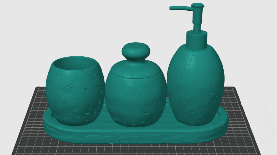
In ceramic design, a plastic print can represent the form of a vase, planter, mug or sculpture before work progresses to ceramic production. It allows proportions, handle space, decorative features and the relationship between separate elements to be assessed at physical scale.
Suitable printed masters can also support mould-making workflows, while printed case moulds can help produce plaster tooling. Surface preparation is important because unwanted layer texture may transfer through the moulding process.
The distinction between a design model and a finished ceramic remains important. A plastic prototype cannot reproduce glaze appearance, firing behaviour or ceramic strength. Shrinkage allowances and final performance must be established using the actual clay body and production process.
Standard and high-quality printing
Different stages of development call for different printing priorities. An early assembly model may need clear dimensions and a usable fit, while a presentation model may place greater emphasis on smooth curves and visible detail.
Layer height is one of the main settings behind standard and high-quality print options. With a 0.4 mm nozzle, an illustrative standard profile might use 0.20 mm layers, while a finer profile might use 0.12–0.16 mm layers. These are examples rather than universal service specifications.
Thinner layers generally reduce the visible stepping on sloping and curved surfaces. They also increase the number of layers needed to complete the object, usually extending printing time and increasing cost. They do not automatically improve every detail: small features in the horizontal plane also depend on nozzle size and the model’s geometry.
Other settings contribute to the result:
| Slicer Setting | Effect on the printed part |
|---|---|
| Layer height | Influences vertical detail, visible layer steps and printing time |
| Walls and infill | Affect construction, material use and mechanical behaviour |
| Printing speed | Can influence surface consistency and visible vibration marks |
| Orientation | Changes support requirements, surface appearance and the direction of the layers relative to a load |
| Supports and seam placement | Affect where contact marks and visible seams appear |
A high-quality surface finish is therefore different from a specification for strength or dimensional fit. A functional bracket may benefit more from an appropriate material and orientation than from finer layers. Conversely, a ceramic concept model intended for a visual review may justify additional printing and finishing time.
FDM 3D printing in Pakistan can therefore serve both as a fabrication service and as part of a wider development process. At Brick3DP, its role alongside design and engineering support is to turn digital models into useful physical parts—from early fitment prototypes to functional assemblies and presentation models.